Rectifier calculator fullwave halfwave maximum average rms voltages. It weakens the ripple.

Full Wave Rectifier And Bridge Rectifier Theory

Diode Applications Half Wave Rectifier And Equivalent

Capacitor Filter Using Half Wave And Full Wave Rectifiers
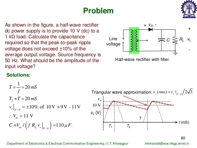
Half wave rectifier with capacitor filter.

Half wave rectifier capacitor calculator. We are given a load of wattage 02w and voltage rating 5v. The problem statement is we need to design a half wave rectifier to power the device up from the main power ac ie 220v. Figure 3 7a shows a half wave rectifier with.
What is a capacitor filter. I can say that the capacitance value should be bauble in half bridge compared to full bridge rectifier because more ripple will appears in half bridge. The main function of the capacitor as well as an inductor in this circuit is a capacitor allows the ac and blocks the dc whereas an inductor permits only dc components to supply and blocks ac.
I mean which size of capacitor should i use. To convert to direct voltage dc a smoothing circuit or filter must be employed. Arduino most popular.
The half wave rectifier is the simplest type of rectifier with a single diode. If a half wave rectifier was used then half the peaks would be missing and the ripple would be approximately twice the voltage. A smoothing capacitor also called a filter capacitor or charging capacitor is used to smooth these voltages.
V m maximum voltage v dc average voltage v rms rms voltage. The half wave rectifier is the simplest type of rectifier with a single diode. For making 100 amperes 50 volts full wave rectifier how do i calculate the circuit capacitance to avoid the ripple voltage.
The output of the rectifier is filtered with a capacitor filter to smoothen. This article discusses capacitor filter using half wave rectifier and full wave rectifier. After a peak in output voltage the capacitor c supplies the current to the load r and continues to do so until the capacitor voltage has fallen to the value of the now rising next half cycle of rectified voltage.
A more common arrangement is to allow the rectifier to work into a large smoothing capacitor which acts as a reservoir. However this circuit has a big disadvantage. Design example of half wave rectifier circuit.
Calculate the load by using the following formula it is 125 ohm which is very low resistance. It is not direct voltage. Experts speak of a high ripple.
How to calculate the half wave rectifier capacitor value there is no prompt formula for capacitor calculationpeople will prefer to fix the value of capacitor practically with help of cro. Peak to peak ripple for output from smoothing capacitor on a power supply full wave the diagram above shows the ripple for a full wave rectifier with capacitor smoothing. It works only from the lower half wave upwards and leaves a pulsating dc voltage.
Half wave rectifier with capacitor filter when a sinusoidal alternating voltage is rectified the resultant waveform is a series of positive or negative half cycles of the input waveform. Rectifiers are the circuit which converts ac voltage to dc voltage.

Basic Power Supply Rectification Tutorial

Online Calculator Linear Power Supply Designer

Capacitor Smoothing Circuits Calculations Electronics Notes

Capacitor Filter Using Half Wave And Full Wave Rectifiers

How To Calculate Filter Capacitor For Smoothing Ripple
Why Is Peak Inverse Voltage 2vp In A Half Way Rectifier With

Introduction To Electronics

Capacitor Smoothing Circuits Calculations Electronics Notes

Half Wave Rectifier Circuit Diagram Theory Applications

Ripple Voltage In Rectifier Circuit All About Circuits

Rectifier Transformer Calculation

Half Wave Rectifier Positive And Negative Half Wave Rectifier
Comments
Post a Comment